A metallographic microscope is used to examine the internal structure of metals and other opaque materials after a specimen has been cut, mounted, ground, polished and etched. Reflected (epi) illumination is directed down through the objective onto the polished surface, so the light that reaches the eyepiece has been reflected by the sample itself.
Yikmo builds upright, inverted and portable metallographic microscopes for quality control laboratories, foundries, heat-treatment shops and failure-analysis teams. The range covers routine brightfield inspection through to darkfield, polarized light and differential interference contrast (DIC).
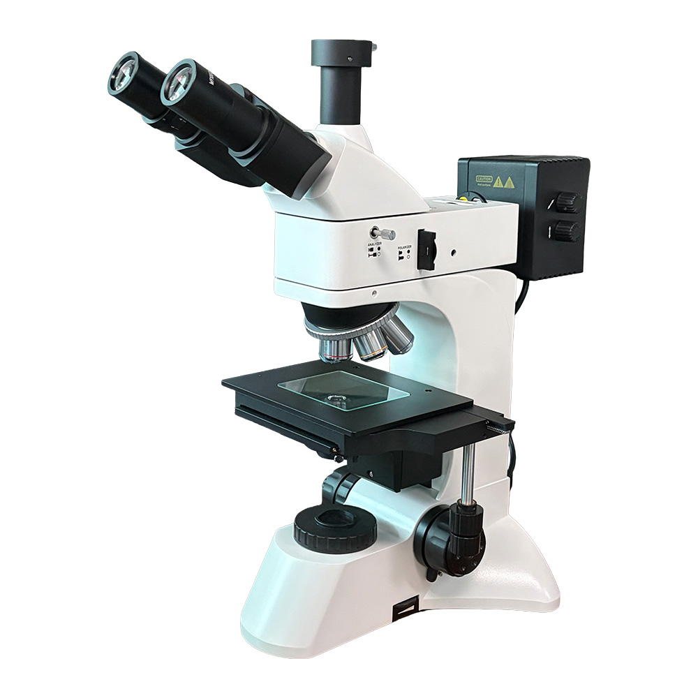
On an upright microscope the objective sits above the stage and looks down at the specimen. It is the standard choice for mounted specimens up to about 40 mm thick, and gives the widest objective selection.
On an inverted microscope the objective is below the stage and looks up. The stage is large and open, so heavy or awkward parts — PCB sections, tube sections, weld coupons — can be placed without clamping. Inverted stands also allow the objective to work through the bottom of a dish or a mounted block.
A portable metallographic microscope is a compact reflected-light unit for field work: weld inspection on site, incoming material checks, or verifying a part that cannot be brought to the lab.
| Magnification | 5×–100× objectives are typical. 50× and 100× dry objectives are used for fine inclusions; 100× oil immersion gives the highest resolution. |
|---|---|
| Illumination | Brightfield is essential. Add darkfield if you inspect scratches, particles or edges; add polarized light for anisotropic phases and coatings; add DIC for surface topography and step heights. |
| Camera | A 12 MP USB 3.0 camera covers most documentation needs. Choose a 4K HDMI camera if operators prefer working without a PC. |
| Stage | A mechanical stage with 75 × 50 mm travel suits mounted specimens. For large parts or wafers, an inverted stand with 150 × 100 mm or more is easier. |
| Software | Measurement software for coating thickness and grain size turns images into numbers you can put in a report. |


100× to 500× total magnification is the usual range for grain size according to ASTM E112 or ISO 643. A 10× or 20× objective with a 10× eyepiece covers most work; 50× is used for fine grains.
Yes. Coatings are measured on a polished cross-section, with a calibrated scale in the eyepiece or with measurement software. Calibration with a stage micrometer is required before measuring.
Not necessarily, but it helps. Inverted stands give a large open stage, so a potted PCB section can be placed without clamping, and the objective can look up at the surface.
In brightfield, light reflected straight back from the surface forms the image, so flat polished areas appear bright. In darkfield, only light scattered at an angle reaches the objective, so flat areas appear dark and edges, scratches and particles appear bright.
Send us the material and what you need to measure. We reply within one business day with a specification and quotation.
